
Transformation of 9 LED Lamps to durable / 12V Design
As many people have seen, mass produced in China is not designed to have a long service life but to seek cheapness.
With a small home improvement, mistakes made during planning can be easily remedied.
(The shape shown on the picture is easily disassembled and can be modified, the front of which is not round but slightly angular, rounded to the inner part of the round type, so it is harder to cut the conductive fibers.)
The lamp is structured as follows:
operates on 3pcs of AAA battery, the negative point of the elements is interrupted by a rubber-coated switch.
The switch connects the batteries to the "-" point with the aluminum cover.
The LEDs (9db) are connected in parallel, their anode legs are twisted at one point (sometimes they are also soldered),
The cathode-side legs lock the circuit to reach the wall of the enclosure.
The problem was that the LEDs were connected in parallel. Since white LEDs have a 3 volt opening voltage (and 9 are never the same), LEDs without current limitation
They burn out quickly (the smallest opening voltage is out first, since most current flows). To avoid this, each of them should have a ballast resistance line.
For disassembling, I found a fairly simple "elegant" solution: a 22mm copper tube is precisely fitted to the lamp casing, allowing you to hit the LEDs from the battery compartment in one motion.

A little math: 3V open-loop, 4.5Volt power supply: difference 1.5V (for good batteries). The rated current of the LEDs is 20mA. From these, Ohm's law follows that
R = U / I, R = 1.5V / 0.02A = 75 Ohms. This resistance value must be aligned with each LED and the lifetime of the lamp will be 50000 to 10000 hours instead of 500-1500 hours.
Since there is not much room for SMD resistors or 0.125W small resistors, it is worth using it.
Since the "smoke" is 1.5V on the resistor, the efficiency is only approx. 2/3 of the battery will be used, but will continue to light up as there is no current flowing.
For use in car, motor or bicycle, this light has been transformed to 12V and since the charging voltage on a battery is 14 to 15 V, so instead of simple resistors
It is advisable to apply a current limiter. The big advantage is that the current consumption is always constant between 10.5 and 20 volts, which maximizes the use of the LEDs and protects them at the same time!
For the current generator there is no need for two "field" transistors (either NPN or PNP) eg. BC546 etc. And 2 resistors. The voltage on the lesser resistance resists one of the transistors,
Which controls the other, so it is easy to calculate the required resistance.
The opening voltage of the transistor is around 0.6V, and the resistance value can easily be calculated from the required current.
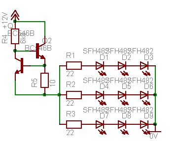
When transforming the lamp, I ended up with the triples of the resistors and these three packs in parallel.
Since the 3d white LED's opening voltage is 3 * 3 = 9V and the voltage of the current generator is approx. 1.2Volt, so only 3 can be connected at the same time.
The opening voltage of the LEDs was 3Volt +/- one tenth of a volt, so the resistance to the line resistance of the 3 groups should be about 0.5V,
So R1, R2, R3 = 0.5V / 0.02A = 25 Ohms (22 or 27 Ohms).
The current generator must produce 3 * 20 = 60mA, therefore the reference resistance is R5 = 0.6V / 0.06A = 10 Ohm
Wiring Diagram about Power Generator Conversion.
Of course, the best solution would be for each LED to work on a separate power generator who has the patience to do so.
If the lamp is operated from a stable 12V then no current generator is needed, but R1 = R2 = R3 = 150 Ohm.
The lamp gives enough light, but radiates at a low angle, so it is suitable for example. For bicycle lighting (even on the back with a red color filter) or, for example, Trabantra reversing lamp, replacement brake light etc ...
Of course, the current generator can be used to test LEDs if the R5 is replaced by 30 (33) ohms.