The
bulb problem often breaks down in Simson
Got a Simson S51b where
the bulb often burns out (Headlamp and rear position
indicator)
Unfortunately, the old coil burned down because a
larger bulb was installed in the headlamp (55Watt was installed).

The
factory Simson S51b headlight bulb is 35 / 35W. There is a metal
baffle around the filament of the passing beam.
For the driving
beam filament, this is not the case. The Simsons generally do not
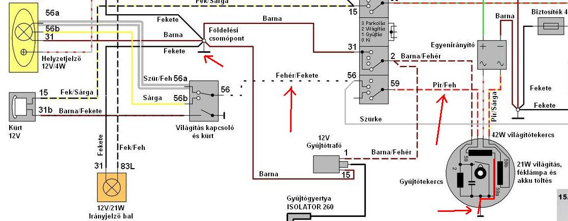
have a voltage regulator for lighting.
As the flywheel rotates,
the magnets on the flywheel induce voltage inside of the lighting
coil.
If we were not connect to anything, it would be up to
60-80V.
Under load, the voltage drops to about 10-15V as a
function of speed.
There's no rectifier or any other electronics,
just the light switch. It is important to have perfect contact
everywhere!
If, for example, The bulb socket on the front bulb
does not contact well, then the bulb on the rear will often go
out!
Always check the switch, as if the contact is faulty, it can
also cause surprises (mostly low brightness and charred switch).
Due
to the lack of electronics, alternating current goes to the bulbs, so
keep that in mind if you want to measure.
(It is worth switching
to 200V AC).
The
factory coil is made of 0.8mm wire, so it has higher resistance, the
new roll is made of 1mm wire and maybe the thread speed is not
exactly the same.
The coil is officially 42W. The front bulb is
35W, the back is 5W. The two together are 40W, 2W is a loss reserve
think ...
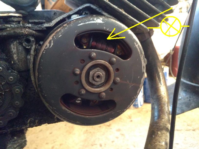
The
one above is the lighting coil (the picture still shows the old burnt
out).
After replacing the burned-out bulbs, I started the
engine (the headlamp does not work when stationary) and then removed
the tail light bulb,
I measured the voltage at the position light
(Here because there is less current and less voltage drop than the
front).
We also need to measure it from the front, because if
there is some contact error in the system, the voltage will be much
lower here.
A few tenths There was a difference between the two
bulbs because of the resistance of the wire.
Holding the
instrument to the terminals, I measured 10.5V, but as soon as I
pulled the throttle, the voltage went up to …
Of course,
the bulb always burned out.
Then came the thought of how to
reduce the tension …
The first thought is
to put up resistance. The problem is that a lot of heat would be
generated, so that would be a very poor solution.
With alternating
voltage on the coil, my second thought was to make a coil that could
be connected in series to limit the current.
I don't like to roll,
I should have iron core too, it gets warm and I should bind it and
then fix it somehow, somewhere …
Not good, I need another
idea.
Let's roll a few threads? This may work
because the tension will be lower if the speed is lower.
The
problem is that I wouldn't like to bundle the enamel wires factory
glued together, then solder them, remove the whole coil …
Should
we put a higher load? Parallel resistance or slightly higher
bulb?
This is not a good idea either, as the coil can burn and the
energy reduces the efficiency of the engine.
Finally,
since the system works so that the magnetic force lines start to
bypass the iron core under load (effect-response),
after a certain
load, the iron core is saturated anyway, the air gap was my next
idea.

The
air gap is defined by the height of the iron.
It provided a
simple solution. If I can increase the air gap, the induction and
voltage will decrease.
This allows the exact voltage to be
set. But the iron core is not adjustable and it would not be good to
drill such a hard material …
Finally, I decided to take off
the flywheel and start using the angle grinder to start increasing
the air gap by grinding the iron core down.
On first run, the
voltage went down to 16V. For the second up to 15.2Volt, the third
managed to set the shaft gas 14.4Volt, which is 10.2V at idle.
This
way, the bulb will certainly not burn out prematurely, since cars are
also designed for 14.4Volt
(12V batteries can be charged up to
14.4Volt, so generators are set up for this).
As you can see this is a
very sensitive operation. You should always grind a little, then
reassemble and measure.
I had to do this 3 times, but it is worth
the time because I don't have to change bulbs anymore.
Many people
install external circuits to protect the bulbs, but I think it's
always easier to have the right solution, as there are no extra parts
or connection points.
I hope I could help others with this
short story.
If you think you should support the site with the
price of a beer or cola, but this is of course optional.
Have a
good ride!
<<
Back <<
2019.11.13.