I have put a dot to the end of a long story.
About three years ago I have get an Sky networks rebagged Netgear DG834GT from my friend Azbeszt.
First of all I have disassembled it, and realized that it has an unsoldered USB port. I have placed the soldered the missing components, (connector, voltage regulator, and the D+ D- protector resistors), but it did not detected any USB devices. I have talked with other people who owns a BCM63XX based routers, and one of them have done this trick on a Comtrend router:
http://img530.imageshack.us/img530/2545 ... 6v2xp2.gifHe notified us, about he had to pull up a pin to enable the port.
I have populated all of the unpopulated pullup resistors place, but I have not succeded.
As the time went on I have purcashed two other unit.
So I have decided to desolder a CPU one of them.
The desoldering was done in my friend's lab.
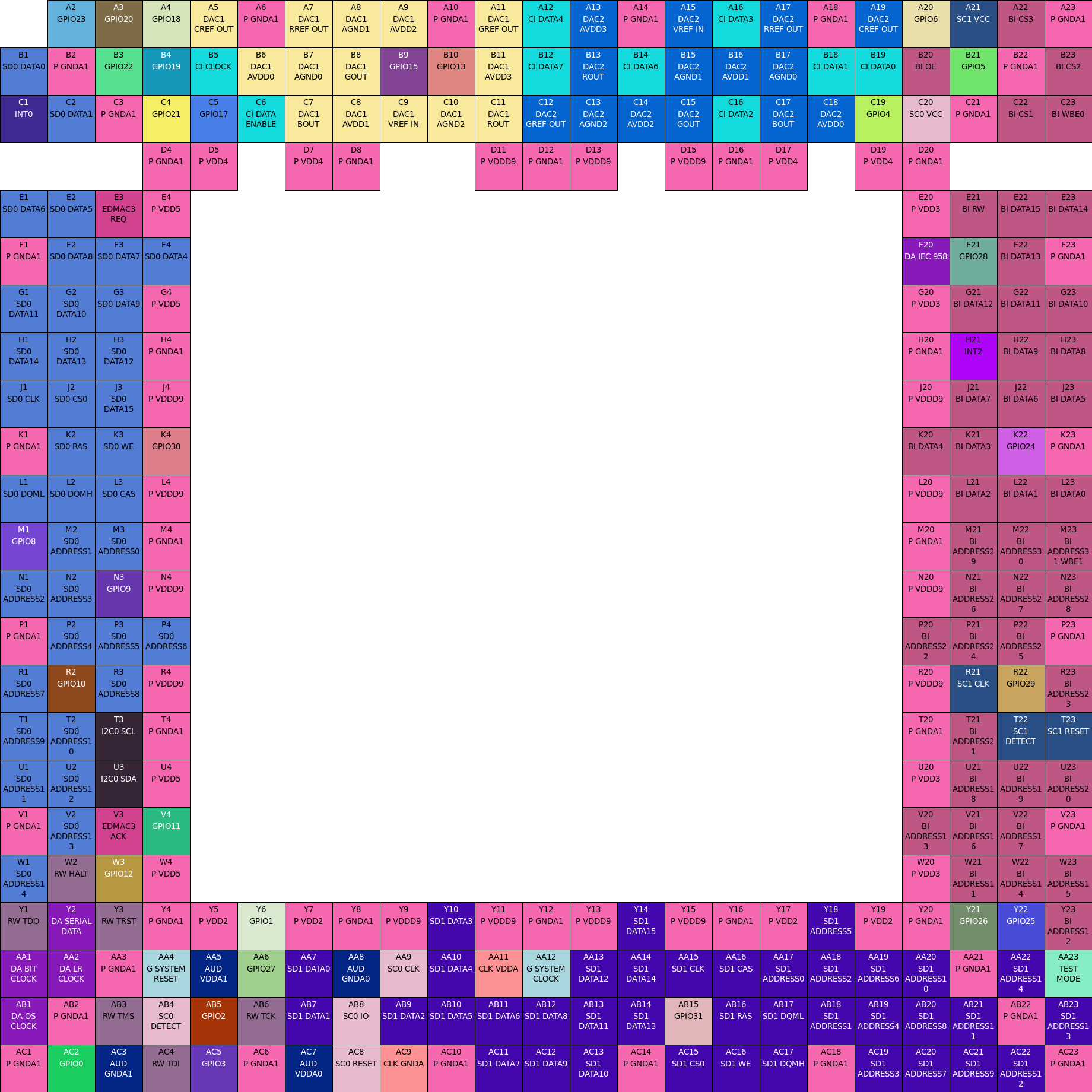
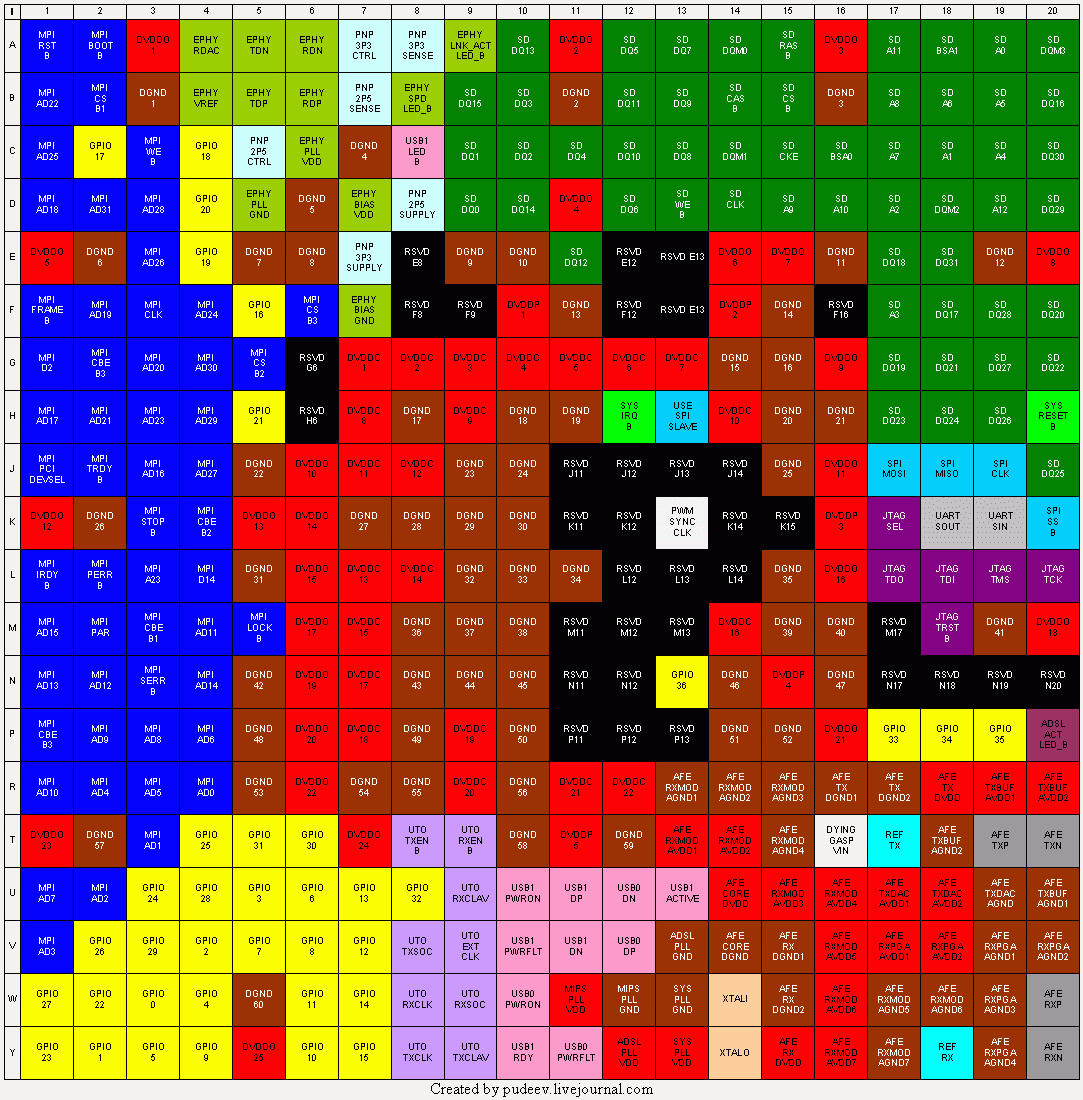
According to this pinout:
http://www.f-x.fr/wikini/wakka.php?wiki=Bcm6348PinOut/Only the D+ D- and the USB_FLT was routed out from the BGA.
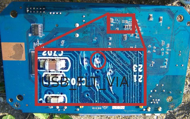
I have traced the USB_FLT trace, but I have not found the other end of the stripe. It does not seems to be connected to anywhere with desoldered CPU. With populetated CPU it has ~90KOhm resistance to the ground. Fortunatelly the trace is connected to an stripe in the inner layer with a trough hole via. So very carefully it is possible to solder a wire to the via.
The via is located in the half way between C702 and C423.
To locate it flip your board to face to the soldering side of the PCB. Rotate it to have the LAN connectors closer to you.
This area will be in the upper side of it:

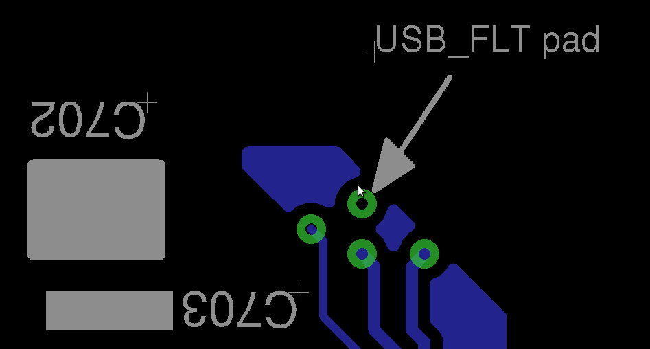
There is a drawing which via is it:

(please note that this is not scale drawing)Solder a thin Cuz wire to it and connect it to the 3V3. The easiest place to find the 3V3 is the serial connector (J503) third pin.
Connect to it with an 2K resistor.
Power up your device, and do
cat /proc/bus/usb/devicesAnd you should see your device details there.
Or you can use the lsusb (from usbutils package).
The additional information about the hack's details could be found here:
http://wiki.openwrt.org/oldwiki/openwrt ... ar/dg834gtCurrently it works for me with an r18196 of the trunk. I will try the bleeding edge version asap.


