My ex-neighbour came to me with an idea which was built around a HVAC fan motor and it's driver. It was salvaged from an old Toshiba air conditioner. You can find a pretty comprehensive service manual for it here. The motor is a ICF-340-30-2 and the driving board is a MCC-821-03 board.
Of course in it's state it was not able to drive the motor as we wanted so I have cut out the original MCU and replaced with an 1 USD STM8S003F3 board:
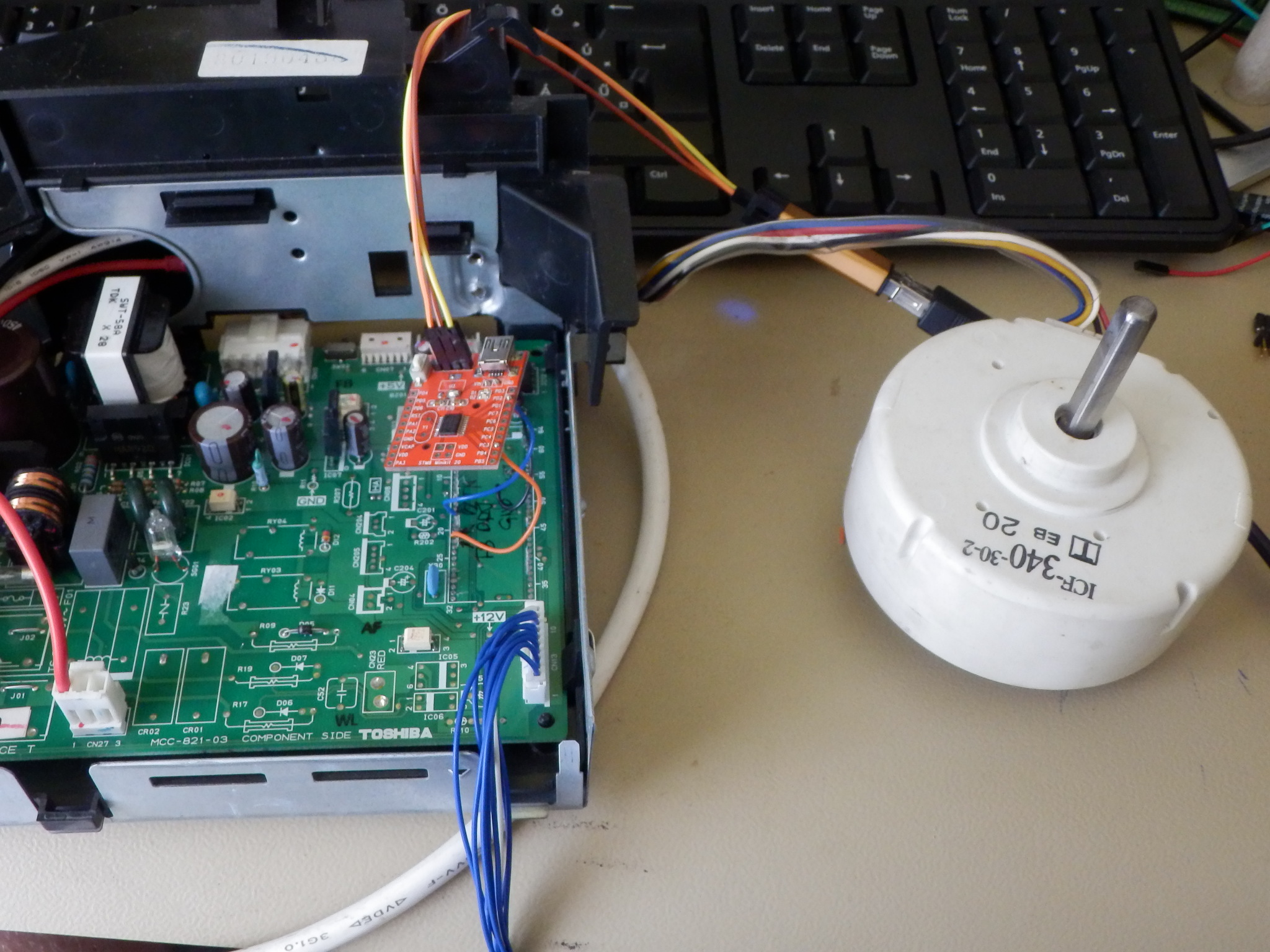
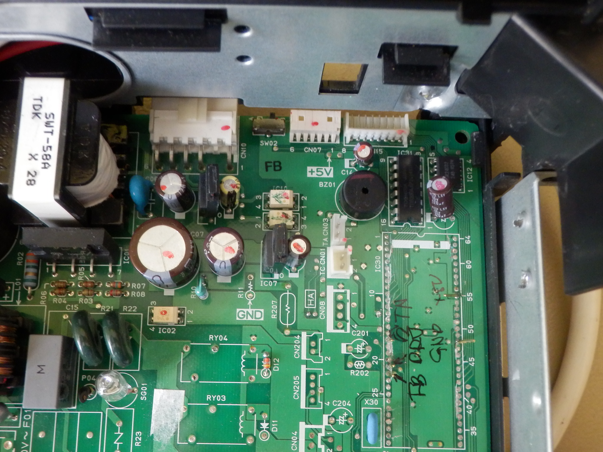
The motor driving is simple: there is a drive and a feedback signal. Both are optically isolated by the IC10 and IC11 optocouplers.
Here is the relevant pins of the main MCU (IC30):
- 21: Drive signal
- 22: Feedback signal
- 17: front button
(VCC (+5V) and GND is accessible from a plenty place)
I have successfully managed to get the motor running by generating an 1.6KHz PWM signal to the drive signal. I have not cared about the feedback signal (closed loop is for the puppies :D)
[ hozzászólás ] ( 190 megtekintés ) [ 0 trackbackek ] permalink Of course in it's state it was not able to drive the motor as we wanted so I have cut out the original MCU and replaced with an 1 USD STM8S003F3 board:
;)
The motor driving is simple: there is a drive and a feedback signal. Both are optically isolated by the IC10 and IC11 optocouplers.
Here is the relevant pins of the main MCU (IC30):
- 21: Drive signal
- 22: Feedback signal
- 17: front button
(VCC (+5V) and GND is accessible from a plenty place)
;)
I have successfully managed to get the motor running by generating an 1.6KHz PWM signal to the drive signal. I have not cared about the feedback signal (closed loop is for the puppies :D)


 ( 2.9 / 8818 )
;)
;)
;)
 \d*)\S*\s*(.*)
;)
;)
;)