Beware of the chinese 5 output chargers sold with 150mAh LiPos! 

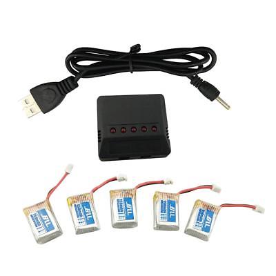
One of my friend bought a similar 5 pack of 150mAh LiPo batteries + 5 output USB charger from ebay for his Furibee F36:


He told me that the batteries bought with it start loosing their capacity after a short period.

He also noticed that the charger charged pretty quickly the at the first cycles too.

After tearing apart the charger we figured out that reason for both thing (the degradation and the fast charge):

There are 5 individual chargers on the PCB built around the LTC4045 IC.


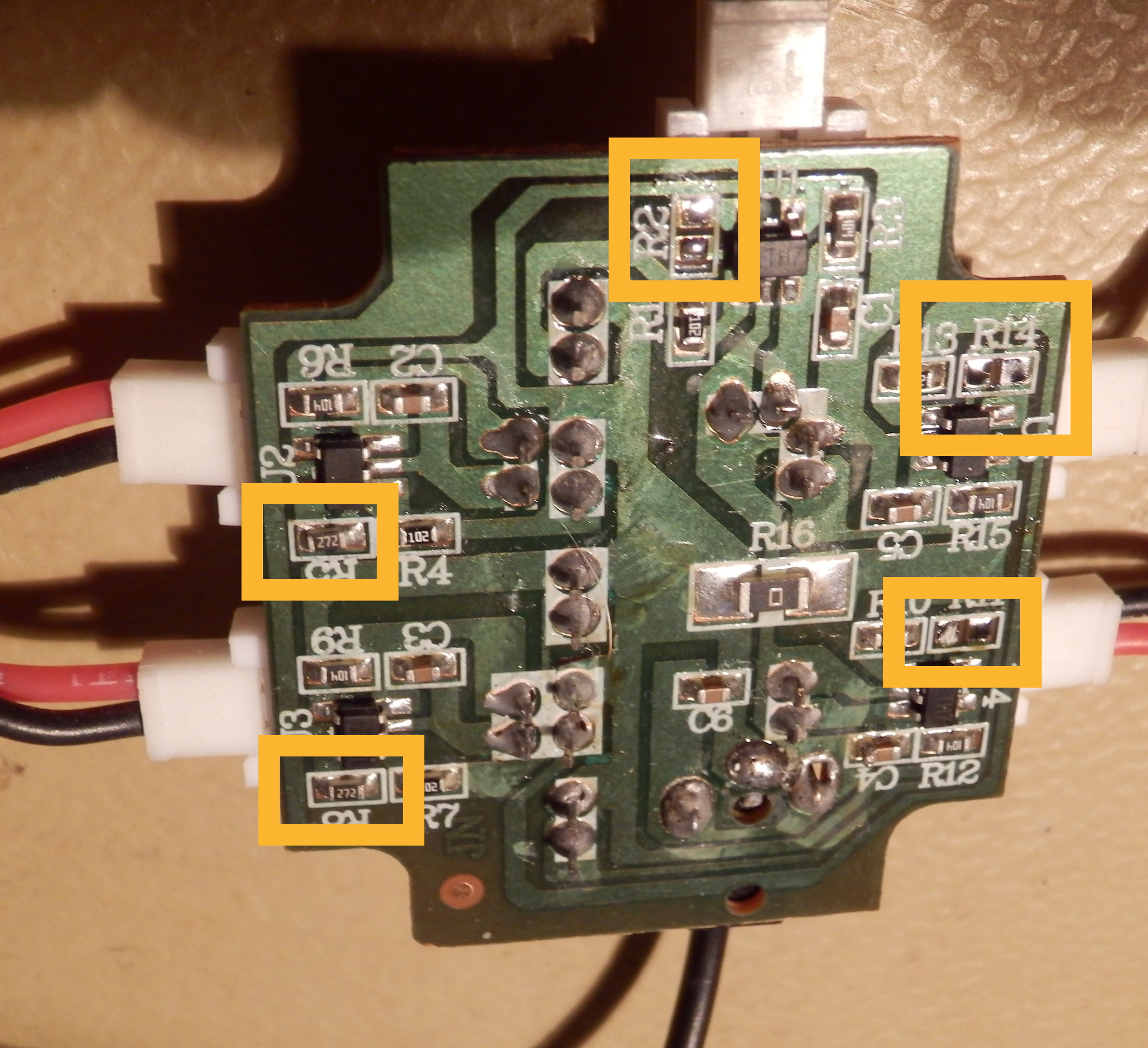
The charging current is controlled by a resistor which was 2700 Ohm in the board.

If we look into the datasheet we find the equation of the charging current:


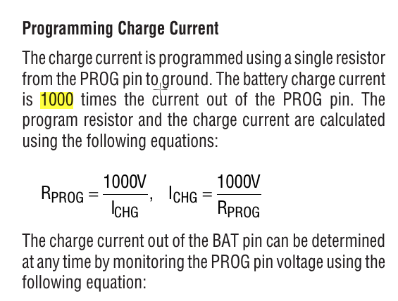
As you can calculate the charging current is set to 1000V/2700Ohm == 370 mA. In the case of a 150mAh battery the charging current is ~2.5C which is pretty high. Usually it is recommended to charge with maximum 1C these batteries.
1C gives us 1000/0.150 == 6666Ohm for prog resistor. It is not so common resistor, so a 6800Ohm (charge current == 147mAh)should fit well.

We wish your batteries long life!

[ hozzászólás ] ( 18 megtekintés ) [ 0 trackbackek ] permalink ( 2.8 / 217 )
DJI Phantom 1 SR6 transmitter teardown 

I have not found any info on the web about this topic, so I was curious what RF frontend did they used.


Solution was obvious: they have used the same as they used in the receiever: the CYRF6936.

I was hoping for having some UART to hook up an Arduino to get trainer output, but I had to get disappointed.

The lower 5 pin connector is the ICE connector of the Nuvoton MINI54ZAN with:
VCC, ICE_DAT, ICE_CLK, !RESET, GND, GND

And the 3 pin is:
P2.3, GND P2.4
[ hozzászólás ] ( 22 megtekintés ) [ 0 trackbackek ] permalink ( 3.1 / 230 )
Nikko C1069C protocol reverse engineering 

I have did some reverse engineering on one of my old Nikko transmitters which is based on the Nikko C1069C ASIC.

My plan is to get rid from the old transmitters and emulate the protocol in a 27 Mhz PPM transmitter with an MCU.

Here are my findings:
The IC sends out the encoded serial signal on pin 2.

Frames sent out with ~30 ms interval.

The frame could be separated to 3 segments:
1st is the steering:
- If steering is in norminal state 168 us L, 1433 us H is sent
- If steering is in right state 168 us L, 3706 us H is sent
- If steering is in left state 168 us L, 252 us H is sent

2nd part is the motor:
- If motor is in norminal state 168 us L, 1433 us H is sent
- If motor is in forward state (no turbo) 168 us L, 252 us H is sent
- If motor is in backward state 168 us L, 3706 us H is sent
- If motor is in forward turbo state 168 us L, 252 us H is sent 168 us L 500 us H is sent

There is a 3rd optional segment the horn:
- If the horn/whatever else button is pressed 168 us L 500 us H 168 us L 500 H sent.

There is a static end part:
- 168 us L 500 us H 168 us L -> H


[ hozzászólás ] ( 39 megtekintés ) [ 0 trackbackek ] permalink ( 3.1 / 283 )
Intex Aqua Fish / Jolla C camera module pinout 

Well the camera module (ST5-YSL500D B-V1) in my phone seems to be died, and since it is not so common phone I cannot buy off the shelf replacement part.

I hope that they used some standardish pinout.

By looking at the layout and doing some measurements here is what I know from the pinout:

+--+-----+-----+-----+-----+----+-----+-----+-----+-----+-----+-----+----+
| | 24 | 23 | 22 | 21 | 20 | 19 | 18 | 17 | 16 | 15 | 14 | 13 |
| | GND | 2V8 | ? | ? | ? | CSI | CSI | CSI | CSI | CSI | CSI | ? |
| | ? | ? | 1V8 | 1V2 | ? | ? | ? | ? | ? | GND | 2V8 | ? |
| | 1 | 2 | 3 | 4 | 5 | 6 | 7 | 8 | 9 | 10 | 11 | 12 |
+--+-----+-----+-----+-----+----+-----+-----+-----+-----+-----+-----+----+

[ hozzászólás ] ( 5 megtekintés ) [ 0 trackbackek ] permalink ( 3 / 287 )
Furibee F36 frame mod for FPV camera mounting 

I have recently purchased a FPV AIO micro camera from Gearbest to hook it to my Furibee F36.

I have tried various mounting options and the mount camera above the mainboard seemed to be the best option. However this gave the some degree of uncertainty to the left-right movements due to the lifted center of gravity. I have decided to modify the frame to be able to place the camera as low as is possible.

After some investigation moving the main PCB right above the battery seemed to be a viable modification. I have estimated to lower the camera mounting position with 5 mm with this mod.

There is a saying in Hungary: if you have a hammer you will threat everything as a nail. This saying also applies to me, but my hammer is my CNC mill. So I have hooked my frame to the mill and removed the necessary parts with it:


I. Remove the battery closing end.
(We are going to install the battery from this end and the battery connector will secure it in the forward-backward direction.)


II. Remove the PCB securing standoff


III. Rasp two V shapes to the PCB to be able to fit properly from the frame's side holders.


IV. After installing the mainboard in the new place drill a 1mm diameter hole to the screws new location, and then install the screws.


V. Cut a bit from the rear screw length because it will cut through the frames plastic and it could hurt the battery.


[ hozzászólás ] ( 264 megtekintés ) [ 0 trackbackek ] permalink ( 3.1 / 306 )

<< <Előző | 7 | 8 | 9 | 10 | 11 | 12 | 13 | 14 | 15 | 16 | Következő> >>

 
számláló