9.2 Sorting Networks
In the quest for fast sorting methods, a number of networks have been designed that sort n elements in time significantly smaller than Q(n log n). These sorting networks are based on a comparison network model, in which many comparison operations are performed simultaneously.
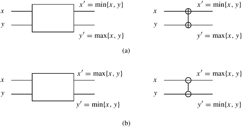
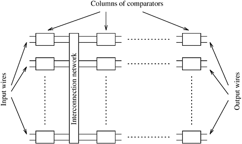
The key component of these networks is a comparator. A comparator is a device with two inputs x and y and two outputs x' and y'. For an increasing comparator, x' = min{x, y} and y' = max{x, y}; for a decreasing comparator x' = max{x, y} and y' = min{x, y}. Figure 9.3 gives the schematic representation of the two types of comparators. As the two elements enter the input wires of the comparator, they are compared and, if necessary, exchanged before they go to the output wires. We denote an increasing comparator by  and a decreasing comparator by and a decreasing comparator by  . A sorting network is usually made up of a series of columns, and each column contains a number of comparators connected in parallel. Each column of comparators performs a permutation, and the output obtained from the final column is sorted in increasing or decreasing order. Figure 9.4 illustrates a typical sorting network. The depth of a network is the number of columns it contains. Since the speed of a comparator is a technology-dependent constant, the speed of the network is proportional to its depth. . A sorting network is usually made up of a series of columns, and each column contains a number of comparators connected in parallel. Each column of comparators performs a permutation, and the output obtained from the final column is sorted in increasing or decreasing order. Figure 9.4 illustrates a typical sorting network. The depth of a network is the number of columns it contains. Since the speed of a comparator is a technology-dependent constant, the speed of the network is proportional to its depth.
We can convert any sorting network into a sequential sorting algorithm by emulating the comparators in software and performing the comparisons of each column sequentially. The comparator is emulated by a compare-exchange operation, where x and y are compared and, if necessary, exchanged.
The following section describes a sorting network that sorts n elements in Q(log2 n) time. To simplify the presentation, we assume that n is a power of two.
9.2.1 Bitonic Sort
A bitonic sorting network sorts n elements in Q(log2 n) time. The key operation of the bitonic sorting network is the rearrangement of a bitonic sequence into a sorted sequence. A bitonic sequence is a sequence of elements <a0, a1, ..., an-1> with the property that either (1) there exists an index i, 0  i i  n - 1, such that <a0, ..., ai > is monotonically increasing and <ai +1, ..., an-1> is monotonically decreasing, or (2) there exists a cyclic shift of indices so that (1) is satisfied. For example, <1, 2, 4, 7, 6, 0> is a bitonic sequence, because it first increases and then decreases. Similarly, <8, 9, 2, 1, 0, 4> is another bitonic sequence, because it is a cyclic shift of <0, 4, 8, 9, 2, 1>. n - 1, such that <a0, ..., ai > is monotonically increasing and <ai +1, ..., an-1> is monotonically decreasing, or (2) there exists a cyclic shift of indices so that (1) is satisfied. For example, <1, 2, 4, 7, 6, 0> is a bitonic sequence, because it first increases and then decreases. Similarly, <8, 9, 2, 1, 0, 4> is another bitonic sequence, because it is a cyclic shift of <0, 4, 8, 9, 2, 1>.
We present a method to rearrange a bitonic sequence to obtain a monotonically increasing sequence. Let s = <a0, a1, ..., an-1> be a bitonic sequence such that a0  a1 a1  ... ...  an/2-1 and an/2 an/2-1 and an/2  an/2+1 an/2+1  ... ...  an-1. Consider the following subsequences of s: an-1. Consider the following subsequences of s:
Equation 9.1

In sequence s1, there is an element bi = min{ai, an/2+i} such that all the elements before bi are from the increasing part of the original sequence and all the elements after bi are from the decreasing part. Also, in sequence s2, the element  is such that all the elements before is such that all the elements before  are from the decreasing part of the original sequence and all the elements after are from the decreasing part of the original sequence and all the elements after  are from the increasing part. Thus, the sequences s1 and s2 are bitonic sequences. Furthermore, every element of the first sequence is smaller than every element of the second sequence. The reason is that bi is greater than or equal to all elements of s1, are from the increasing part. Thus, the sequences s1 and s2 are bitonic sequences. Furthermore, every element of the first sequence is smaller than every element of the second sequence. The reason is that bi is greater than or equal to all elements of s1,  is less than or equal to all elements of s2, and is less than or equal to all elements of s2, and  is greater than or equal to bi. Thus, we have reduced the initial problem of rearranging a bitonic sequence of size n to that of rearranging two smaller bitonic sequences and concatenating the results. We refer to the operation of splitting a bitonic sequence of size n into the two bitonic sequences defined by Equation 9.1 as a bitonic split. Although in obtaining s1 and s2 we assumed that the original sequence had increasing and decreasing sequences of the same length, the bitonic split operation also holds for any bitonic sequence (Problem 9.3). is greater than or equal to bi. Thus, we have reduced the initial problem of rearranging a bitonic sequence of size n to that of rearranging two smaller bitonic sequences and concatenating the results. We refer to the operation of splitting a bitonic sequence of size n into the two bitonic sequences defined by Equation 9.1 as a bitonic split. Although in obtaining s1 and s2 we assumed that the original sequence had increasing and decreasing sequences of the same length, the bitonic split operation also holds for any bitonic sequence (Problem 9.3).
We can recursively obtain shorter bitonic sequences using Equation 9.1 for each of the bitonic subsequences until we obtain subsequences of size one. At that point, the output is sorted in monotonically increasing order. Since after each bitonic split operation the size of the problem is halved, the number of splits required to rearrange the bitonic sequence into a sorted sequence is log n. The procedure of sorting a bitonic sequence using bitonic splits is called bitonic merge. The recursive bitonic merge procedure is illustrated in Figure 9.5.

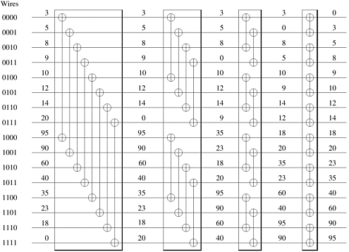
We now have a method for merging a bitonic sequence into a sorted sequence. This method is easy to implement on a network of comparators. This network of comparators, known as a bitonic merging network, it is illustrated in Figure 9.6. The network contains log n columns. Each column contains n/2 comparators and performs one step of the bitonic merge. This network takes as input the bitonic sequence and outputs the sequence in sorted order. We denote a bitonic merging network with n inputs by  BM[n]. If we replace the BM[n]. If we replace the  comparators in Figure 9.6 by comparators in Figure 9.6 by  comparators, the input will be sorted in monotonically decreasing order; such a network is denoted by comparators, the input will be sorted in monotonically decreasing order; such a network is denoted by  BM[n]. BM[n].
Armed with the bitonic merging network, consider the task of sorting n unordered elements. This is done by repeatedly merging bitonic sequences of increasing length, as illustrated in Figure 9.7.
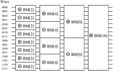
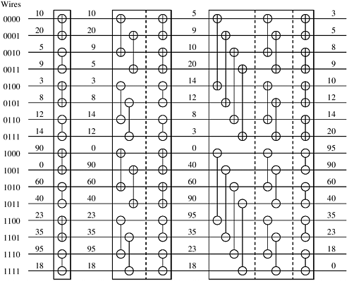
Let us now see how this method works. A sequence of two elements x and y forms a bitonic sequence, since either x  y, in which case the bitonic sequence has x and y in the increasing part and no elements in the decreasing part, or x y, in which case the bitonic sequence has x and y in the increasing part and no elements in the decreasing part, or x  y, in which case the bitonic sequence has x and y in the decreasing part and no elements in the increasing part. Hence, any unsorted sequence of elements is a concatenation of bitonic sequences of size two. Each stage of the network shown in Figure 9.7 merges adjacent bitonic sequences in increasing and decreasing order. According to the definition of a bitonic sequence, the sequence obtained by concatenating the increasing and decreasing sequences is bitonic. Hence, the output of each stage in the network in Figure 9.7 is a concatenation of bitonic sequences that are twice as long as those at the input. By merging larger and larger bitonic sequences, we eventually obtain a bitonic sequence of size n. Merging this sequence sorts the input. We refer to the algorithm embodied in this method as bitonic sort and the network as a bitonic sorting network. The first three stages of the network in Figure 9.7 are shown explicitly in Figure 9.8. The last stage of Figure 9.7 is shown explicitly in Figure 9.6. y, in which case the bitonic sequence has x and y in the decreasing part and no elements in the increasing part. Hence, any unsorted sequence of elements is a concatenation of bitonic sequences of size two. Each stage of the network shown in Figure 9.7 merges adjacent bitonic sequences in increasing and decreasing order. According to the definition of a bitonic sequence, the sequence obtained by concatenating the increasing and decreasing sequences is bitonic. Hence, the output of each stage in the network in Figure 9.7 is a concatenation of bitonic sequences that are twice as long as those at the input. By merging larger and larger bitonic sequences, we eventually obtain a bitonic sequence of size n. Merging this sequence sorts the input. We refer to the algorithm embodied in this method as bitonic sort and the network as a bitonic sorting network. The first three stages of the network in Figure 9.7 are shown explicitly in Figure 9.8. The last stage of Figure 9.7 is shown explicitly in Figure 9.6.
The last stage of an n-element bitonic sorting network contains a bitonic merging network with n inputs. This has a depth of log n. The other stages perform a complete sort of n/2 elements. Hence, the depth, d(n), of the network in Figure 9.7 is given by the following recurrence relation:
Equation 9.2

Solving Equation 9.2, we obtain  . This network can be implemented on a serial computer, yielding a Q(n log2 n) sorting algorithm. The bitonic sorting network can also be adapted and used as a sorting algorithm for parallel computers. In the next section, we describe how this can be done for hypercube-and mesh-connected parallel computers. . This network can be implemented on a serial computer, yielding a Q(n log2 n) sorting algorithm. The bitonic sorting network can also be adapted and used as a sorting algorithm for parallel computers. In the next section, we describe how this can be done for hypercube-and mesh-connected parallel computers.
9.2.2 Mapping Bitonic Sort to a Hypercube and a Mesh
In this section we discuss how the bitonic sort algorithm can be mapped on general-purpose parallel computers. One of the key aspects of the bitonic algorithm is that it is communication intensive, and a proper mapping of the algorithm must take into account the topology of the underlying interconnection network. For this reason, we discuss how the bitonic sort algorithm can be mapped onto the interconnection network of a hypercube- and mesh-connected parallel computers.
The bitonic sorting network for sorting n elements contains log n stages, and stage i consists of i columns of n/2 comparators. As Figures 9.6 and 9.8 show, each column of comparators performs compare-exchange operations on n wires. On a parallel computer, the compare-exchange function is performed by a pair of processes.
One Element Per Process
In this mapping, each of the n processes contains one element of the input sequence. Graphically, each wire of the bitonic sorting network represents a distinct process. During each step of the algorithm, the compare-exchange operations performed by a column of comparators are performed by n/2 pairs of processes. One important question is how to map processes to wires in order to minimize the distance that the elements travel during a compare-exchange operation. If the mapping is poor, the elements travel a long distance before they can be compared, which will degrade performance. Ideally, wires that perform a compare-exchange should be mapped onto neighboring processes. Then the parallel formulation of bitonic sort will have the best possible performance over all the formulations that require n processes.
To obtain a good mapping, we must further investigate the way that input wires are paired during each stage of bitonic sort. Consider Figures 9.6 and 9.8, which show the full bitonic sorting network for n = 16. In each of the (1 + log 16)(log 16)/2 = 10 comparator columns, certain wires compare-exchange their elements. Focus on the binary representation of the wire labels. In any step, the compare-exchange operation is performed between two wires only if their labels differ in exactly one bit. During each of the four stages, wires whose labels differ in the least-significant bit perform a compare-exchange in the last step of each stage. During the last three stages, wires whose labels differ in the second-least-significant bit perform a compare-exchange in the second-to-last step of each stage. In general, wires whose labels differ in the ith least-significant bit perform a compare-exchange (log n - i + 1) times. This observation helps us efficiently map wires onto processes by mapping wires that perform compare-exchange operations more frequently to processes that are close to each other.
Hypercube
Mapping wires onto the processes of a hypercube-connected parallel computer is straightforward. Compare-exchange operations take place between wires whose labels differ in only one bit. In a hypercube, processes whose labels differ in only one bit are neighbors (Section 2.4.3). Thus, an optimal mapping of input wires to hypercube processes is the one that maps an input wire with label l to a process with label l where l = 0, 1, ..., n - 1.
Consider how processes are paired for their compare-exchange steps in a d-dimensional hypercube (that is, p = 2d). In the final stage of bitonic sort, the input has been converted into a bitonic sequence. During the first step of this stage, processes that differ only in the dth bit of the binary representation of their labels (that is, the most significant bit) compare-exchange their elements. Thus, the compare-exchange operation takes place between processes along the dth dimension. Similarly, during the second step of the algorithm, the compare-exchange operation takes place among the processes along the (d - 1)th dimension. In general, during the ith step of the final stage, processes communicate along the (d - (i - 1))th dimension. Figure 9.9 illustrates the communication during the last stage of the bitonic sort algorithm.
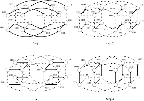
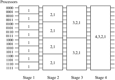
A bitonic merge of sequences of size 2k can be performed on a k-dimensional subcube, with each such sequence assigned to a different subcube (Problem 9.5). Furthermore, during the ith step of this bitonic merge, the processes that compare their elements are neighbors along the (k - (i - 1))th dimension. Figure 9.10 is a modification of Figure 9.7, showing the communication characteristics of the bitonic sort algorithm on a hypercube.
The bitonic sort algorithm for a hypercube is shown in Algorithm 9.1. The algorithm relies on the functions comp_exchange_max(i) and comp_exchange_min(i). These functions compare the local element with the element on the nearest process along the ith dimension and retain either the minimum or the maximum of the two elements. Problem 9.6 explores the correctness of Algorithm 9.1.
Algorithm 9.1 Parallel formulation of bitonic sort on a hypercube with n = 2d processes. In this algorithm, label is the process's label and d is the dimension of the hypercube.
1.   procedure BITONIC_SORT(label, d)
2.   begin
3.      for i := 0 to d - 1 do
4.          for j := i downto 0 do
5.              if (i + 1)st bit of label  jth bit of label then
6.                   comp_exchange max(j);
7.              else
8.                  comp_exchange min(j);
9. end BITONIC_SORT jth bit of label then
6. comp_exchange max(j);
7. else
8. comp_exchange min(j);
9. end BITONIC_SORT
During each step of the algorithm, every process performs a compare-exchange operation. The algorithm performs a total of (1 + log n)(log n)/2 such steps; thus, the parallel run time is
Equation 9.3

This parallel formulation of bitonic sort is cost optimal with respect to the sequential implementation of bitonic sort (that is, the process-time product is Q(n log2 n)), but it is not cost-optimal with respect to an optimal comparison-based sorting algorithm, which has a serial time complexity of Q(n log n).
Mesh
Consider how the input wires of the bitonic sorting network can be mapped efficiently onto an n-process mesh. Unfortunately, the connectivity of a mesh is lower than that of a hypercube, so it is impossible to map wires to processes such that each compare-exchange operation occurs only between neighboring processes. Instead, we map wires such that the most frequent compare-exchange operations occur between neighboring processes.
There are several ways to map the input wires onto the mesh processes. Some of these are illustrated in Figure 9.11. Each process in this figure is labeled by the wire that is mapped onto it. Of these three mappings, we concentrate on the row-major shuffled mapping, shown in Figure 9.11(c). We leave the other two mappings as exercises (Problem 9.7).
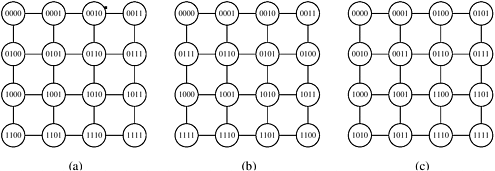
The advantage of row-major shuffled mapping is that processes that perform compare-exchange operations reside on square subsections of the mesh whose size is inversely related to the frequency of compare-exchanges. For example, processes that perform compare-exchange during every stage of bitonic sort (that is, those corresponding to wires that differ in the least-significant bit) are neighbors. In general, wires that differ in the ith least-significant bit are mapped onto mesh processes that are  communication links away. The compare-exchange steps of the last stage of bitonic sort for the row-major shuffled mapping are shown in Figure 9.12. Note that each earlier stage will have only some of these steps. communication links away. The compare-exchange steps of the last stage of bitonic sort for the row-major shuffled mapping are shown in Figure 9.12. Note that each earlier stage will have only some of these steps.

During the (1 + log n)(log n)/2 steps of the algorithm, processes that are a certain distance apart compare-exchange their elements. The distance between processes determines the communication overhead of the parallel formulation. The total amount of communication performed by each process is  , which is Q( , which is Q( ) (Problem 9.7). During each step of the algorithm, each process performs at most one comparison; thus, the total computation performed by each process is Q(log2 n). This yields a parallel run time of ) (Problem 9.7). During each step of the algorithm, each process performs at most one comparison; thus, the total computation performed by each process is Q(log2 n). This yields a parallel run time of

This is not a cost-optimal formulation, because the process-time product is Q(n1.5), but the sequential complexity of sorting is Q(n log n). Although the parallel formulation for a hypercube was optimal with respect to the sequential complexity of bitonic sort, the formulation for mesh is not. Can we do any better? No. When sorting n elements, one per mesh process, for certain inputs the element stored in the process at the upper-left corner will end up in the process at the lower-right corner. For this to happen, this element must travel along  communication links before reaching its destination. Thus, the run time of sorting on a mesh is bounded by W( communication links before reaching its destination. Thus, the run time of sorting on a mesh is bounded by W( ). Our parallel formulation achieves this lower bound; thus, it is asymptotically optimal for the mesh architecture. ). Our parallel formulation achieves this lower bound; thus, it is asymptotically optimal for the mesh architecture.
A Block of Elements Per Process
In the parallel formulations of the bitonic sort algorithm presented so far, we assumed there were as many processes as elements to be sorted. Now we consider the case in which the number of elements to be sorted is greater than the number of processes.
Let p be the number of processes and n be the number of elements to be sorted, such that p < n. Each process is assigned a block of n/p elements and cooperates with the other processes to sort them. One way to obtain a parallel formulation with our new setup is to think of each process as consisting of n/p smaller processes. In other words, imagine emulating n/p processes by using a single process. The run time of this formulation will be greater by a factor of n/p because each process is doing the work of n/p processes. This virtual process approach (Section 5.3) leads to a poor parallel implementation of bitonic sort. To see this, consider the case of a hypercube with p processes. Its run time will be Q((n log2 n)/p), which is not cost-optimal because the process-time product is Q(n log2 n).
An alternate way of dealing with blocks of elements is to use the compare-split operation presented in Section 9.1. Think of the (n/p)-element blocks as elements to be sorted using compare-split operations. The problem of sorting the p blocks is identical to that of performing a bitonic sort on the p blocks using compare-split operations instead of compare-exchange operations (Problem 9.8). Since the total number of blocks is p, the bitonic sort algorithm has a total of (1 + log p)(log p)/2 steps. Because compare-split operations preserve the initial sorted order of the elements in each block, at the end of these steps the n elements will be sorted. The main difference between this formulation and the one that uses virtual processes is that the n/p elements assigned to each process are initially sorted locally, using a fast sequential sorting algorithm. This initial local sort makes the new formulation more efficient and cost-optimal.
Hypercube
The block-based algorithm for a hypercube with p processes is similar to the one-element-per-process case, but now we have p blocks of size n/p, instead of p elements. Furthermore, the compare-exchange operations are replaced by compare-split operations, each taking Q(n/p) computation time and Q(n/p) communication time. Initially the processes sort their n/p elements (using merge sort) in time Q((n/p) log(n/p)) and then perform Q(log2 p) compare-split steps. The parallel run time of this formulation is

Because the sequential complexity of the best sorting algorithm is Q(n log n), the speedup and efficiency are as follows:
Equation 9.4

From Equation 9.4, for a cost-optimal formulation (log2 p)/(log n) = O(1). Thus, this algorithm can efficiently use up to  processes. Also from Equation 9.4, the isoefficiency function due to both communication and extra work is Q(plog p log2 p), which is worse than any polynomial isoefficiency function for sufficiently large p. Hence, this parallel formulation of bitonic sort has poor scalability. processes. Also from Equation 9.4, the isoefficiency function due to both communication and extra work is Q(plog p log2 p), which is worse than any polynomial isoefficiency function for sufficiently large p. Hence, this parallel formulation of bitonic sort has poor scalability.
Mesh
The block-based mesh formulation is also similar to the one-element-per-process case. The parallel run time of this formulation is as follows:

Note that comparing the communication overhead of this mesh-based parallel bitonic sort  to the communication overhead of the hypercube-based formulation (O((n log2 p)/p)), we can see that it is higher by a factor of to the communication overhead of the hypercube-based formulation (O((n log2 p)/p)), we can see that it is higher by a factor of  . This factor is smaller than the . This factor is smaller than the  difference in the bisection bandwidth of these architectures. This illustrates that a proper mapping of the bitonic sort on the underlying mesh can achieve better performance than that achieved by simply mapping the hypercube algorithm on the mesh. difference in the bisection bandwidth of these architectures. This illustrates that a proper mapping of the bitonic sort on the underlying mesh can achieve better performance than that achieved by simply mapping the hypercube algorithm on the mesh.
The speedup and efficiency are as follows:
Equation 9.5

Table 9.1. The performance of parallel formulations of bitonic sort for n elements on p processes.|
|
Hypercube |

|

|
Q(plog p log2 p) | |
Mesh |
Q(log2 n) |
Q(n/ log n) |

| |
Ring |
Q(log n) |
Q(n) |
Q(2p p) |
From Equation 9.5, for a cost-optimal formulation  . Thus, this formulation can efficiently use up to p = Q(log2 n) processes. Also from Equation 9.5, the isoefficiency function . Thus, this formulation can efficiently use up to p = Q(log2 n) processes. Also from Equation 9.5, the isoefficiency function  . The isoefficiency function of this formulation is exponential, and thus is even worse than that for the hypercube. . The isoefficiency function of this formulation is exponential, and thus is even worse than that for the hypercube.
From the analysis for hypercube and mesh, we see that parallel formulations of bitonic sort are neither very efficient nor very scalable. This is primarily because the sequential algorithm is suboptimal. Good speedups are possible on a large number of processes only if the number of elements to be sorted is very large. In that case, the efficiency of the internal sorting outweighs the inefficiency of the bitonic sort. Table 9.1 summarizes the performance of bitonic sort on hypercube-, mesh-, and ring-connected parallel computer.
 |
![]() . Thus, this formulation can efficiently use up to p = Q(log2 n) processes. Also from Equation 9.5, the isoefficiency function
. Thus, this formulation can efficiently use up to p = Q(log2 n) processes. Also from Equation 9.5, the isoefficiency function ![]() . The isoefficiency function of this formulation is exponential, and thus is even worse than that for the hypercube.
. The isoefficiency function of this formulation is exponential, and thus is even worse than that for the hypercube.