13.3 The Transpose Algorithm
The binary-exchange algorithm yields good performance on parallel computers with sufficiently high communication bandwidth with respect to the processing speed of the CPUs. Efficiencies below a certain threshold can be maintained while increasing the problem size at a moderate rate with an increasing number of processes. However, this threshold is very low if the communication bandwidth of the parallel computer is low compared to the speed of its processors. In this section, we describe a different parallel formulation of FFT that trades off some efficiency for a more consistent level of parallel performance. This parallel algorithm involves matrix transposition, and hence is called the transpose algorithm.
The performance of the transpose algorithm is worse than that of the binary-exchange algorithm for efficiencies below the threshold. However, it is much easier to obtain efficiencies above the binary-exchange algorithm's threshold using the transpose algorithm. Thus, the transpose algorithm is particularly useful when the ratio of communication bandwidth to CPU speed is low and high efficiencies are desired. On a hypercube or a p-node network with Q(p) bisection width, the transpose algorithm has a fixed asymptotic isoefficiency function of Q(p2 log p). That is, the order of this isoefficiency function is independent of the ratio of the speed of point-to-point communication and the computation.
13.3.1 Two-Dimensional Transpose Algorithm
The simplest transpose algorithm requires a single transpose operation over a two-dimensional array; hence, we call this algorithm the two-dimensional transpose algorithm.
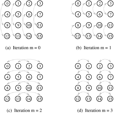
Assume that  is a power of 2, and that the sequences of size n used in Algorithm 13.2 are arranged in a is a power of 2, and that the sequences of size n used in Algorithm 13.2 are arranged in a  two-dimensional square array, as shown in Figure 13.8 for n = 16. Recall that computing the FFT of a sequence of n points requires log n iterations of the outer loop of Algorithm 13.2. If the data are arranged as shown in Figure 13.8, then the FFT computation in each column can proceed independently for log two-dimensional square array, as shown in Figure 13.8 for n = 16. Recall that computing the FFT of a sequence of n points requires log n iterations of the outer loop of Algorithm 13.2. If the data are arranged as shown in Figure 13.8, then the FFT computation in each column can proceed independently for log  iterations without any column requiring data from any other column. Similarly, in the remaining log iterations without any column requiring data from any other column. Similarly, in the remaining log  iterations, computation proceeds independently in each row without any row requiring data from any other row. Figure 13.8 shows the pattern of combination of the elements for a 16-point FFT. The figure illustrates that if data of size n are arranged in a iterations, computation proceeds independently in each row without any row requiring data from any other row. Figure 13.8 shows the pattern of combination of the elements for a 16-point FFT. The figure illustrates that if data of size n are arranged in a  array, then an n-point FFT computation is equivalent to independent array, then an n-point FFT computation is equivalent to independent  -point FFT computations in the columns of the array, followed by independent -point FFT computations in the columns of the array, followed by independent  -point FFT computations in the rows. -point FFT computations in the rows.
If the  array of data is transposed after computing the array of data is transposed after computing the  -point column FFTs, then the remaining part of the problem is to compute the -point column FFTs, then the remaining part of the problem is to compute the  -point columnwise FFTs of the transposed matrix. The transpose algorithm uses this property to compute the FFT in parallel by using a columnwise striped partitioning to distribute the -point columnwise FFTs of the transposed matrix. The transpose algorithm uses this property to compute the FFT in parallel by using a columnwise striped partitioning to distribute the  array of data among the processes. For instance, consider the computation of the 16-point FFT shown in Figure 13.9, where the 4 x 4 array of data is distributed among four processes such that each process stores one column of the array. In general, the two-dimensional transpose algorithm works in three phases. In the first phase, a array of data among the processes. For instance, consider the computation of the 16-point FFT shown in Figure 13.9, where the 4 x 4 array of data is distributed among four processes such that each process stores one column of the array. In general, the two-dimensional transpose algorithm works in three phases. In the first phase, a  -point FFT is computed for each column. In the second phase, the array of data is transposed. The third and final phase is identical to the first phase, and involves the computation of -point FFT is computed for each column. In the second phase, the array of data is transposed. The third and final phase is identical to the first phase, and involves the computation of  -point FFTs for each column of the transposed array. Figure 13.9 shows that the first and third phases of the algorithm do not require any interprocess communication. In both these phases, all -point FFTs for each column of the transposed array. Figure 13.9 shows that the first and third phases of the algorithm do not require any interprocess communication. In both these phases, all  points for each columnwise FFT computation are available on the same process. Only the second phase requires communication for transposing the points for each columnwise FFT computation are available on the same process. Only the second phase requires communication for transposing the  matrix. matrix.
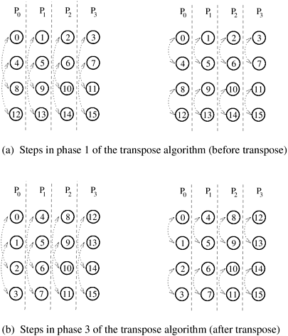
In the transpose algorithm shown in Figure 13.9, one column of the data array is assigned to one process. Before analyzing the transpose algorithm further, consider the more general case in which p processes are used and 1  p p   . The . The  array of data is striped into blocks, and one block of array of data is striped into blocks, and one block of  rows is assigned to each process. In the first and third phases of the algorithm, each process computes rows is assigned to each process. In the first and third phases of the algorithm, each process computes  FFTs of size FFTs of size  each. The second phase transposes the each. The second phase transposes the  matrix, which is distributed among p processes with a one-dimensional partitioning. Recall from Section 4.5 that such a transpose requires an all-to-all personalized communication. matrix, which is distributed among p processes with a one-dimensional partitioning. Recall from Section 4.5 that such a transpose requires an all-to-all personalized communication.
Now we derive an expression for the parallel run time of the two-dimensional transpose algorithm. The only inter-process interaction in this algorithm occurs when the  array of data partitioned along columns or rows and mapped onto p processes is transposed. Replacing the message size m by n/p - the amount of data owned by each process - in the expression for all-to-all personalized communication in Table 4.1 yields ts (p - 1) + twn/p as the time spent in the second phase of the algorithm. The first and third phases each take time array of data partitioned along columns or rows and mapped onto p processes is transposed. Replacing the message size m by n/p - the amount of data owned by each process - in the expression for all-to-all personalized communication in Table 4.1 yields ts (p - 1) + twn/p as the time spent in the second phase of the algorithm. The first and third phases each take time  . Thus, the parallel run time of the transpose algorithm on a hypercube or any Q(p) bisection width network is given by the following equation: . Thus, the parallel run time of the transpose algorithm on a hypercube or any Q(p) bisection width network is given by the following equation:
Equation 13.11

The expressions for speedup and efficiency are as follows:
Equation 13.12

The process-time product of this parallel system is tcn log n + ts p2 + twn. This parallel system is cost-optimal if n log n = W(p2 log p).
Note that the term associated with tw in the expression for efficiency in Equation 13.12 is independent of the number of processes. The degree of concurrency of this algorithm requires that  because at most because at most  processes can be used to partition the processes can be used to partition the  array of data in a striped manner. As a result, n = W(p2), or n log n = W(p2 log p). Thus, the problem size must increase at least as fast as Q(p2 log p) with respect to the number of processes to use all of them efficiently. The overall isoefficiency function of the two-dimensional transpose algorithm is Q(p2 log p) on a hypercube or another interconnection network with bisection width Q(p). This isoefficiency function is independent of the ratio of tw for point-to-point communication and tc. On a network whose cross-section bandwidth b is less than Q(p) for p nodes, the tw term must be multiplied by an appropriate expression of Q(p/b) in order to derive TP, S, E, and the isoefficiency function (Problem 13.6). array of data in a striped manner. As a result, n = W(p2), or n log n = W(p2 log p). Thus, the problem size must increase at least as fast as Q(p2 log p) with respect to the number of processes to use all of them efficiently. The overall isoefficiency function of the two-dimensional transpose algorithm is Q(p2 log p) on a hypercube or another interconnection network with bisection width Q(p). This isoefficiency function is independent of the ratio of tw for point-to-point communication and tc. On a network whose cross-section bandwidth b is less than Q(p) for p nodes, the tw term must be multiplied by an appropriate expression of Q(p/b) in order to derive TP, S, E, and the isoefficiency function (Problem 13.6).
Comparison with the Binary-Exchange Algorithm
A comparison of Equations 13.4 and 13.11 shows that the transpose algorithm has a much higher overhead than the binary-exchange algorithm due to the message startup time ts, but has a lower overhead due to per-word transfer time tw. As a result, either of the two algorithms may be faster depending on the relative values of ts and tw. If the latency ts is very low, then the transpose algorithm may be the algorithm of choice. On the other hand, the binary-exchange algorithm may perform better on a parallel computer with a high communication bandwidth but a significant startup time.
Recall from Section 13.2.1 that an overall isoefficiency function of Q(p log p) can be realized by using the binary-exchange algorithm if the efficiency is such that Ktw/tc  1, where K = E /(1 - E). If the desired efficiency is such that Ktw/tc = 2, then the overall isoefficiency function of both the binary-exchange and the two-dimensional transpose algorithms is Q(p2 log p). When Ktw/tc > 2, the two-dimensional transpose algorithm is more scalable than the binary-exchange algorithm; hence, the former should be the algorithm of choice, provided that n 1, where K = E /(1 - E). If the desired efficiency is such that Ktw/tc = 2, then the overall isoefficiency function of both the binary-exchange and the two-dimensional transpose algorithms is Q(p2 log p). When Ktw/tc > 2, the two-dimensional transpose algorithm is more scalable than the binary-exchange algorithm; hence, the former should be the algorithm of choice, provided that n  p2. Note, however, that the transpose algorithm yields a performance benefit over the binary-exchange algorithm only if the target architecture has a cross-section bandwidth of Q(p) for p nodes (Problem 13.6). p2. Note, however, that the transpose algorithm yields a performance benefit over the binary-exchange algorithm only if the target architecture has a cross-section bandwidth of Q(p) for p nodes (Problem 13.6).
13.3.2 The Generalized Transpose Algorithm
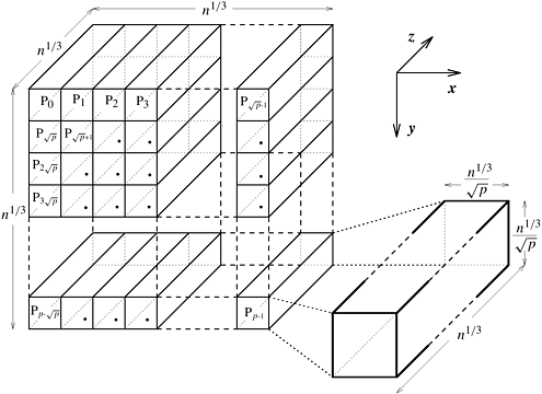
In the two-dimensional transpose algorithm, the input of size n is arranged in a  two-dimensional array that is partitioned along one dimension on p processes. These processes, irrespective of the underlying architecture of the parallel computer, can be regarded as arranged in a logical one-dimensional linear array. As an extension of this scheme, consider the n data points to be arranged in an n1/3 x n1/3 x n1/3 three-dimensional array mapped onto a logical two-dimensional array that is partitioned along one dimension on p processes. These processes, irrespective of the underlying architecture of the parallel computer, can be regarded as arranged in a logical one-dimensional linear array. As an extension of this scheme, consider the n data points to be arranged in an n1/3 x n1/3 x n1/3 three-dimensional array mapped onto a logical  two-dimensional mesh of processes. Figure 13.10 illustrates this mapping. To simplify the algorithm description, we label the three axes of the three-dimensional array of data as x, y, and z. In this mapping, the x-y plane of the array is checkerboarded into two-dimensional mesh of processes. Figure 13.10 illustrates this mapping. To simplify the algorithm description, we label the three axes of the three-dimensional array of data as x, y, and z. In this mapping, the x-y plane of the array is checkerboarded into  parts. As the figure shows, each process stores parts. As the figure shows, each process stores  columns of data, and the length of each column (along the z-axis) is n1/3. Thus, each process has columns of data, and the length of each column (along the z-axis) is n1/3. Thus, each process has  elements of data. elements of data.
Recall from Section 13.3.1 that the FFT of a two-dimensionally arranged input of size  can be computed by first computing the can be computed by first computing the  -point one-dimensional FFTs of all the columns of the data and then computing the -point one-dimensional FFTs of all the columns of the data and then computing the  -point one-dimensional FFTs of all the rows. If the data are arranged in an n1/3 x n1/3 x n1/3 three-dimensional array, the entire n-point FFT can be computed similarly. In this case, n1/3-point FFTs are computed over the elements of the columns of the array in all three dimensions, choosing one dimension at a time. We call this algorithm the three-dimensional transpose algorithm. This algorithm can be divided into the following five phases: -point one-dimensional FFTs of all the rows. If the data are arranged in an n1/3 x n1/3 x n1/3 three-dimensional array, the entire n-point FFT can be computed similarly. In this case, n1/3-point FFTs are computed over the elements of the columns of the array in all three dimensions, choosing one dimension at a time. We call this algorithm the three-dimensional transpose algorithm. This algorithm can be divided into the following five phases:
In the first phase, n1/3-point FFTs are computed on all the rows along the z-axis. In the second phase, all the n1/3 cross-sections of size n1/3 x n1/3 along the y-z plane are transposed. In the third phase, n1/3-point FFTs are computed on all the rows of the modified array along the z-axis. In the fourth phase, each of the n1/3 x n1/3 cross-sections along the x-z plane is transposed. In the fifth and final phase, n1/3-point FFTs of all the rows along the z-axis are computed again.
For the data distribution shown in Figure 13.10, in the first, third, and fifth phases of the algorithm, all processes perform  FFT computations, each of size n1/3. Since all the data for performing these computations are locally available on each process, no interprocess communication is involved in these three odd-numbered phases. The time spent by a process in each of these phases is FFT computations, each of size n1/3. Since all the data for performing these computations are locally available on each process, no interprocess communication is involved in these three odd-numbered phases. The time spent by a process in each of these phases is  . Thus, the total time that a process spends in computation is tc(n/p) log n. . Thus, the total time that a process spends in computation is tc(n/p) log n.
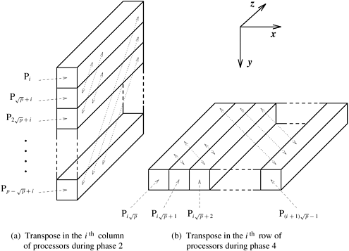
Figure 13.11 illustrates the second and fourth phases of the three-dimensional transpose algorithm. As Figure 13.11(a) shows, the second phase of the algorithm requires transposing square cross-sections of size n1/3 x n1/3 along the y-z plane. Each column of  processes performs the transposition of processes performs the transposition of  such cross-sections. This transposition involves all-to-all personalized communications among groups of such cross-sections. This transposition involves all-to-all personalized communications among groups of  processes with individual messages of size n/p3/2. If a p-node network with bisection width Q(p) is used, this phase takes time processes with individual messages of size n/p3/2. If a p-node network with bisection width Q(p) is used, this phase takes time  . The fourth phase, shown in Figure 13.11(b), is similar. Here each row of . The fourth phase, shown in Figure 13.11(b), is similar. Here each row of  processes performs the transpose of processes performs the transpose of  cross-sections along the x-z plane. Again, each cross-section consists of n1/3 x n1/3 data elements. The communication time of this phase is the same as that of the second phase. The total parallel run time of the three-dimensional transpose algorithm for an n-point FFT is cross-sections along the x-z plane. Again, each cross-section consists of n1/3 x n1/3 data elements. The communication time of this phase is the same as that of the second phase. The total parallel run time of the three-dimensional transpose algorithm for an n-point FFT is
Equation 13.13

Having studied the two- and three-dimensional transpose algorithms, we can derive a more general q-dimensional transpose algorithm similarly. Let the n-point input be arranged in a logical q-dimensional array of size n1/q x n1/q x···xn1/q (a total of q terms). Now the entire n-point FFT computation can be viewed as q subcomputations. Each of the q subcomputations along a different dimension consists of n(q-1)/q FFTs over n1/q data points. We map the array of data onto a logical (q - 1)-dimensional array of p processes, where p  n(q-1)/q, and p = 2(q-1)s for some integer s. The FFT of the entire data is now computed in (2q - 1) phases (recall that there are three phases in the two-dimensional transpose algorithm and five phases in the three-dimensional transpose algorithm). In the q odd-numbered phases, each process performs n(q-1)/q/p of the required n1/q-point FFTs. The total computation time for each process over all q computation phases is the product of q (the number of computation phases), n(q-1)/q/p (the number of n1/q-point FFTs computed by each process in each computation phase), and tcn1/q log(n1/q) (the time to compute a single n1/q-point FFT). Multiplying these terms gives a total computation time of tc(n/p) log n. n(q-1)/q, and p = 2(q-1)s for some integer s. The FFT of the entire data is now computed in (2q - 1) phases (recall that there are three phases in the two-dimensional transpose algorithm and five phases in the three-dimensional transpose algorithm). In the q odd-numbered phases, each process performs n(q-1)/q/p of the required n1/q-point FFTs. The total computation time for each process over all q computation phases is the product of q (the number of computation phases), n(q-1)/q/p (the number of n1/q-point FFTs computed by each process in each computation phase), and tcn1/q log(n1/q) (the time to compute a single n1/q-point FFT). Multiplying these terms gives a total computation time of tc(n/p) log n.
In each of the (q - 1) even-numbered phases, sub-arrays of size n1/q x n1/q are transposed on rows of the q-dimensional logical array of processes. Each such row contains p1/(q-1) processes. One such transpose is performed along every dimension of the (q - 1)-dimensional process array in each of the (q - 1) communication phases. The time spent in communication in each transposition is ts(p1/(q-1) - 1) + twn/p. Thus, the total parallel run time of the q-dimensional transpose algorithm for an n-point FFT on a p-node network with bisection width Q(p) is
Equation 13.14

Equation 13.14 can be verified by replacing q with 2 and 3, and comparing the result with Equations 13.11 and 13.13, respectively.
A comparison of Equations 13.11, 13.13, 13.14, and 13.4 shows an interesting trend. As the dimension q of the transpose algorithm increases, the communication overhead due to tw increases, but that due to ts decreases. The binary-exchange algorithm and the two-dimensional transpose algorithms can be regarded as two extremes. The former minimizes the overhead due to ts but has the largest overhead due to tw. The latter minimizes the overhead due to tw but has the largest overhead due to ts . The variations of the transpose algorithm for 2 < q < log p lie between these two extremes. For a given parallel computer, the specific values of tc, ts , and tw determine which of these algorithms has the optimal parallel run time (Problem 13.8).
Note that, from a practical point of view, only the binary-exchange algorithm and the two- and three-dimensional transpose algorithms are feasible. Higher-dimensional transpose algorithms are very complicated to code. Moreover, restrictions on n and p limit their applicability. These restrictions for a q-dimensional transpose algorithm are that n must be a power of two that is a multiple of q, and that p must be a power of 2 that is a multiple of (q - 1). In other words, n = 2qr, and p = 2(q-1)s, where q, r, and s are integers.
Example 13.2 A comparison of binary-exchange, 2-D transpose, and 3-D transpose algorithms
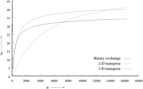
This example shows that either the binary-exchange algorithm or any of the transpose algorithms may be the algorithm of choice for a given parallel computer, depending on the size of the FFT. Consider a 64-node version of the hypercube described in Example 13.1 with tc = 2, ts = 25, and tw = 4. Figure 13.12 shows speedups attained by the binary-exchange algorithm, the 2-D transpose algorithm, and the 3-D transpose algorithm for different problem sizes. The speedups are based on the parallel run times given by Equations 13.4, 13.11, and 13.13, respectively. The figure shows that for different ranges of n, a different algorithm provides the highest speedup for an n-point FFT. For the given values of the hardware parameters, the binary-exchange algorithm is best suited for very low granularity FFT computations, the 2-D transpose algorithm is best for very high granularity computations, and the 3-D transpose algorithm's speedup is the maximum for intermediate granularities. 
 |